A smart terrarium light for around $20
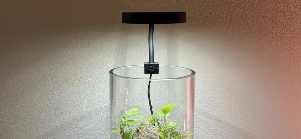
The cheapest and best-reviewed aquarium/terrarium light on Amazon is unfortunately not possible to control with an outlet timer or smart plug, as it does not turn on when power is applied regardless of its previous state.
One reviewer figured out how to accomplish this by bypassing the control circuitry entirely, but this also bypasses the adjustable PWM dimming performed by the controller. This means it runs the lights at full brightness, which started killing off the moss in the terrarium.
I started designing my own control circuitry, but it turns out the LEDs are controlled by modulating the connection between their anodes and ground, and I just didn’t have the energy to spec out and order MOSFETs (or perhaps “MOSS”-FETs, in this particular application) to drive them. However, it was very easy to find a 2-channel LED controller and wire them up, achieving the same effect.
Bill of materials
These links are not affiliate links, so there’s no difference to me if you use them or not.
| Item | Price | Purchase link |
|---|---|---|
| DOMICA Clip-on dimmable light | $9.99 | Amazon |
| GLEDOPTO 2-channel ZigBee LED controller | $11.38 | AliExpress |
| USB power adapter (at least 1A) | Check your junk drawer | |
| Total | $21.37 |
A note about the power adapter: the white and RGB channels use around 1A each, but the controller mixes between the channels and doesn’t allow both to run at full brightness, so a 1A USB power supply should be sufficient if you’re modifying it this way. To use the light with the built-in controller, use at least a 2A power supply to avoid drawing too much current and starting a fire if both channels ever end up running at the same time. I’m personally using a Verizon-branded one that’s probably old enough to drive.
Ripping into it
I actually purchased both variants of the light: one with a built-in timer and one without. I used the timer variant until I modified the dimmer-only variant to be “smart”, and let’s just say those poor plants didn’t get light every day. But forgetfulness is why we’re here!
I didn’t care about destroying the controller’s plastic housing, so I just pried it open with the screwdriver that came with my 2nd-gen Nest thermostat. Other flathead screwdrivers should work fine too, but I can’t say for sure because I’ve been using this one exclusively for the last 10 years.
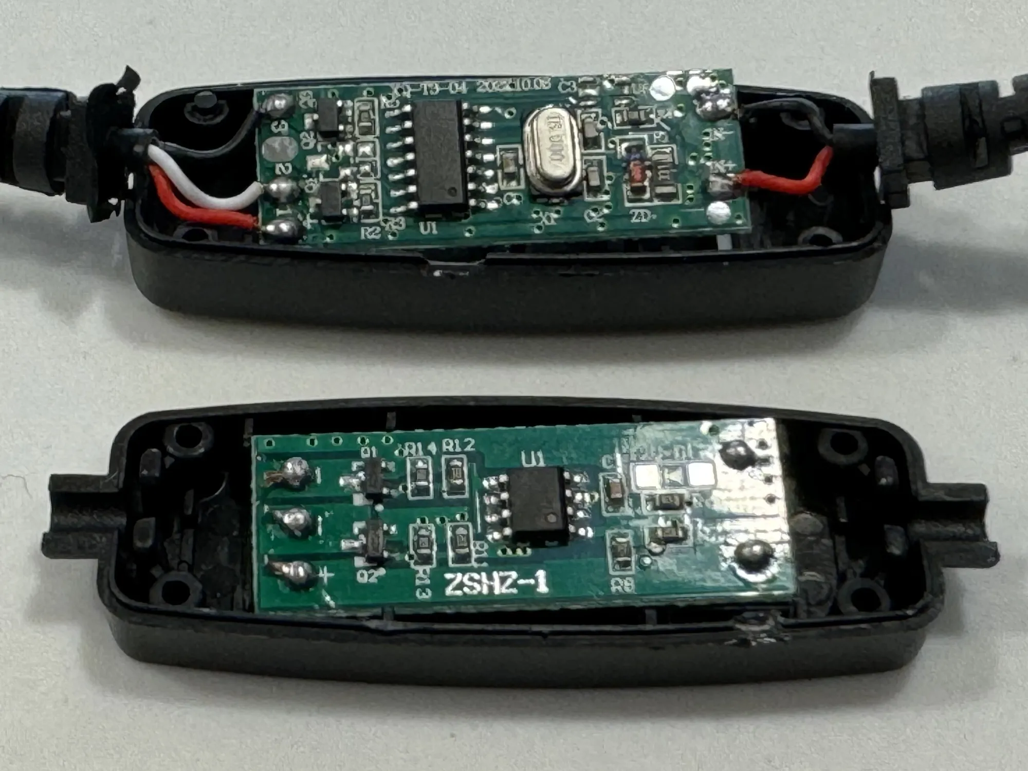
This step is unnecessary once you know the wire colors because the next step is to cut the cables from either side of the controller and strip back all the wires, which don’t particularly care if you opened the controller or not.
Wiring
With each of the two cables you just cut off of the controller, cut back the outer black casing from the cut end by about 10 mm, then use a wire stripper to remove about 5mm of insulation from the end of each of the wires inside.
Wiring into the lighting controller was a new and exciting experience for me; I’d never seen this type of wire gripping mechanism, and I hope never to see it again. For each wire, you have to press the punchdown-like tool included with the controller into the top hole really hard to slightly separate the metal fins while inserting the wire into the hole on the side, then remove the tool and gently pull on the wire to make sure it’s fully inserted.
USB power input
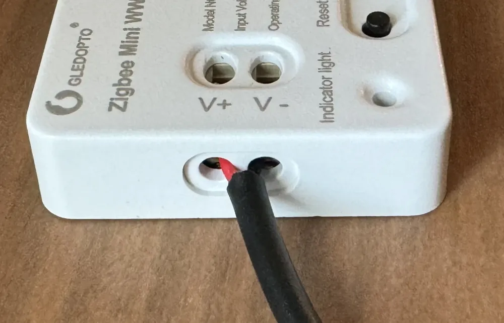
| Wire color | Controller pin |
|---|---|
| Black | V- |
| Red | V+ |
If you have a 5V 1A center-positive barrel jack power supply sitting around, you could wire in the barrel jack receptacle included with the controller instead of reusing the USB cable.
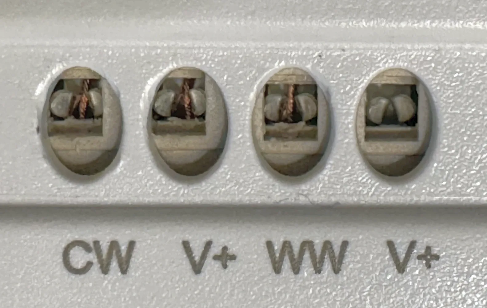
LED outputs
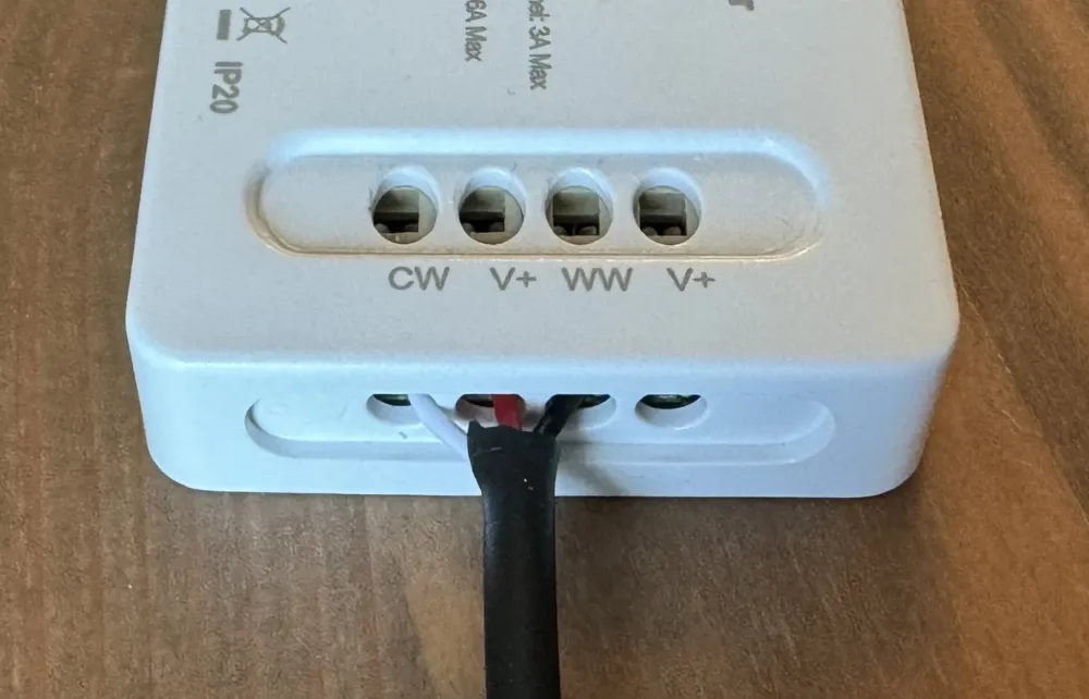
If your lamp is like my two, the wire colors are as follows:
| Wire color | Purpose | Controller pin |
|---|---|---|
| White | Color LEDs | CW |
| Red | Power supply | V+ |
| Black | White LEDs | WW |
| (Not connected) | Power supply | V+ |
I used the V+ connector between the two channel outputs, but you could probably use either one since the manual, which I didn’t read until now, says to use the other one:
Software
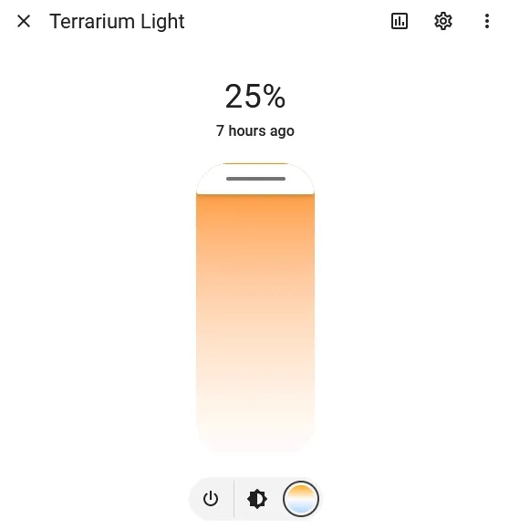
I use Zigbee2MQTT to manage my Zigbee network and integrate it with Home Assistant, so I just clicked “enable join” at the top, plugged in the controller to USB power, and it showed right up.
For normal people who don’t run a home server, the controller also claims to work with Hue bridges and Alexa devices.
If you are running Home Assistant, I use the following automation to turn the light on to 25% brightness at 11:30 and off at 19:00 with a 5-minute fade each way:
alias: Terrarium Light Schedule
trigger:
  - platform: time
    at: "11:30:00"
    id: "On"
  - platform: time
    at: "19:00:00"
    id: "Off"
action:
  - choose:
      - conditions:
          - condition: trigger
            id: ["On"]
        sequence:
          - service: light.turn_on
            data:
              color_temp: 500
              transition: 300
              brightness_pct: 25
            target:
              entity_id: light.terrarium_light
      - conditions:
          - condition: trigger
            id: ["Off"]
        sequence:
          - service: light.turn_off
            data:
              transition: 300
            target:
              entity_id: light.terrarium_light
OTA update breaks the controller
At some point in early-to-mid 2024, Zigbee2MQTT added an over-the-air (OTA) update for the GL-C-006P controllers. Unfortunately, Zigbee2MQTT’s OTA update process cannot distinguish between the “normal” and “mini” versions of the controller, and the output pins are different, so applying the wrong update will prevent it from controlling the lights.
The mini controller I used received the normal controller’s firmware update and would no longer respond to light commands. Fixing it required flashing two modified firmware images, as provided and documented by Andrik45719 on GitHub.
Comments ()