Projector control
The backstory: Many years ago, I bought an old Sanyo PLC-XU48 from Craigslist for $50. Since then, I’ve used it as a TV to watch videos and movies and play games. The resolution (1024x768) isn’t great by today’s standards, but at a distance it’s fine for my use.
The problem: Recently, the power button on the remote has decided to only work a tiny fraction of the time, which is really frustrating when trying to double-press it to turn off the projector.
First attempt at a solution: A new remote? Boring. Serial is much more exciting! I have some Particle Photon boards, which are Arduino-like microcontrollers with WiFi and I wanted to use one to communicate with the projector through its serial “SERVICE” port instead of using the remote. This would also let me integrate it with Home Assistant or write a web interface.
But where to start? I had no idea how to use this port. Luckily, I wasn’t the first to try this. I found “Projector Controllers for Sanyo Projectors”, an old SourceForge project, that attempted to do the same thing. This told me that the service port was an 8-pin mini-DIN serial port. As for my specific model, I found several “serial command manuals” (such as the one linked below for the Sanyo PLC-XU106) that detailed the serial protocol and commands. They were all similar enough (differing only in the number of commands available, which makes sense given the different models have different features) so I assumed the basic on, off, and input switching commands would work with my projector.
Using this knowledge, I found and ordered a breakout connector (shown and linked below) that would let me use such a cable into with my microcontroller boards, and a serial cable to go between it and the projector’s service port.

My projector’s manual did provide a little bit of useful information: the service port pin numbering and assignment (shown below)
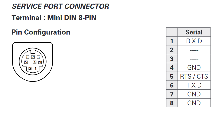
Combining this with the datasheet for the breakout connector from Mouser (linked below), I created this mapping table:
| Projector | Number | Color | Arduino |
|---|---|---|---|
| RXD | 1 | Brown | TX (3) |
| — | 2 | White | — |
| — | 3 | Black | — |
| GND | 4 | Blue | — |
| RTS/CTS | 5 | Green | ? |
| TXD | 6 | Yellow | RX (2) |
| GND | 7 | Orange | — |
| GND | 8 | Red | GND |
Despite the presence of an RTS/CTS line, the manual says that flow control is not needed.
Now I had everything I needed to communicate with the projector using an Arduino Uno I had laying around. I wrote the following sketch to be able to write my own data out and receive incoming data while sending the required CR between commands:
#include <SoftwareSerial.h>

SoftwareSerial projector(2, 3);

char buffer[64];
byte index = 0;

void setup() {
  Serial.begin(19200);
  while (!Serial);

  projector.begin(19200);
  while (!projector);

  Serial.write("Ready\n");
}

void loop() {
  // Projector -> PC
  if (projector.available()) {
    Serial.write("RX: ");

    while (projector.available()) {
      Serial.write(projector.read());
    }

    Serial.write('\n');
  }

  // PC -> Projector
  while (Serial.available()) {
    char c = Serial.read();

    if (c == '\r' || c == '\n') {
      // Send buffer to projector
      projector.write(buffer, index);
      projector.write(0x0D);

      // Echo buffer
      Serial.write("TX: ");
      Serial.write(buffer, index);
      Serial.write('\n');

      // Reset buffer
      index = 0;
    } else {
      // Add to buffer
      buffer[index++] = c;
    }
  }
}
But did it work? No. I sent many commands through the serial console and got left on read an equal number of times.
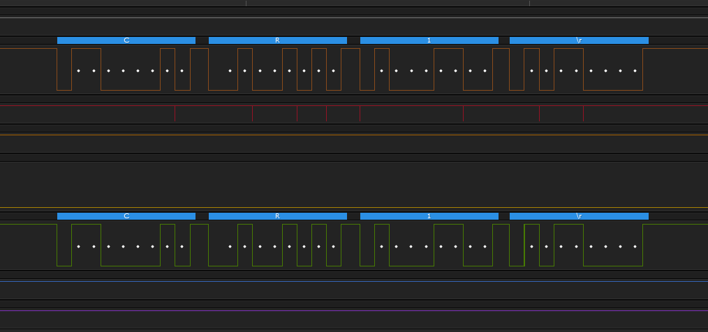
To figure out what was going on, I hooked up a logic analyzer to all of the lines and recorded sending messages from the Arduino and waiting for a response, as shown here:
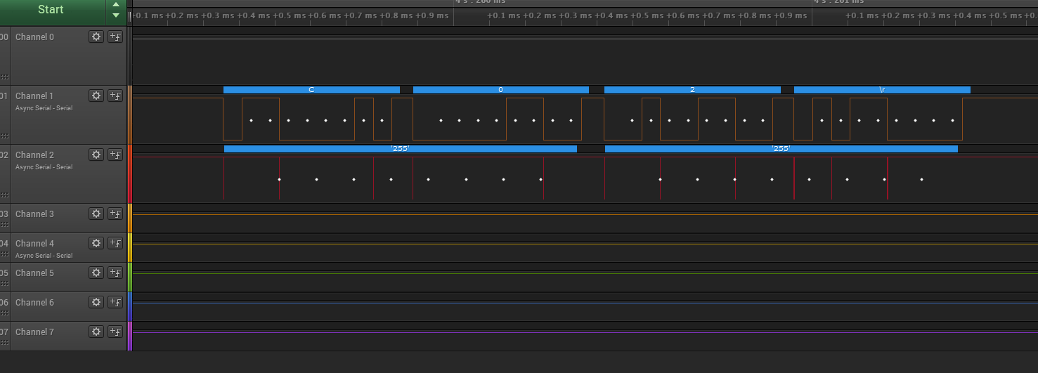
C02\r sent and only line noise receivedI’m not sure what the ‘255’ on the GND line was from, but I’m assuming it was just crosstalk due to the cheap breadboard I was using.
After another couple hours of trying different combinations of wires and serial data, I figured it must be the incorrect voltage. The Arduino was only communicating with 5 volts, but RS-232 could go much higher. If the projector was expecting 12 volts, it wouldn’t count 5 volts as a signal. Before sending higher voltages into my projector without knowing, I decided to email the person behind the Projector Controller project on SourceForge that I mentioned earlier. I figured it was a long shot that the email was still valid because it had been 10 years since the project was last active, but I was desperate.
I sent an email asking about what voltages were tested and working, and to my surprise, I got a response, and quickly! The relevant part:
Its been a while since I looked at this. In my circuit I used a max232 level converter chip, so I’m guessing its 12v. It should be reasonably safe to try this. In my other software project I would have used a usb to serial converter which also would likely be 12v.
Looks like I was right. Unfortunately, the level converter chips aren’t cheap, and I had already spent about $15 on this project, so I assumed I was probably nearing the cost of a new remote and decided to give up. But wait…remotes? I already had an input to the projector that works, I just need something besides my remote to use it!
What comes in packs full of matching pairs for about half the price of a MAX232 chip? IR diodes just like the one in my remote. Into my cart they went.
Stay tuned to find out what happens when they arrive!
Even though I didn’t get this method working, I documented my work anyway in case it is helpful to someone who is willing to buy a MAX232 chip and use the correct voltages. The PDFs I linked to are also hosted on this site in an effort to save others from the constant barrage of 404 errors I experienced while tracking them down.
Comments ()